
When a block model or wireframe has been created or stored in a rotated mine grid, directly editing the X, Y, Z fields will distort the geometry. This happens because the rotation is stored in metadata, not in the coordinates themselves. Any attempt to shift or overwrite coordinates simply applies changes after the rotation transform — resulting in stretching, skewing, or warped block shapes.
Plane Grid Conversion is the correct workflow for removing this rotation and restoring the model cleanly into real-world space.
What Plane Grid Conversion Actually Does
Plane Grid Conversion computes a least-squares transformation between two coordinate systems (A → B) based on matching control points.
It applies one consistent transform across the entire dataset:
XY rotation
XY translation
Optional XY scale
Optional Z shift
Because the transform is uniform and rigid, the model retains its true shape — no distortion.
How It Works
1. Common Points
You provide 1, 2, or preferably 3+ matched points between Grid A and Grid B.
The tool calculates the optimal transformation.
Points can be picked interactively (Pick Point, lasso, polygon).
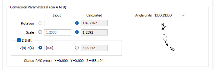
2. Conversion Parameters
The form shows both calculated and optional manual inputs for:
Rotation (DDD.MMSS or DDD.DDDD)
Scale
Z-shift
Values and residuals update instantly.
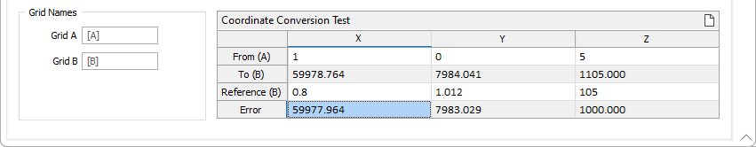
3. Testing & Saving
The Coordinate Conversion Test grid lets you enter sample coordinates to preview the transformed results and error values.
You can also save the entire setup as a reusable form — useful when repeating conversions across updates or multiple wireframes.
4. Converting Files or Wireframes
After setting the transform:
Convert File: applies the transform to every point in a point file.
Convert Wireframe: applies the transform to an entire wireframe and optionally saves a new output wireframe.
This is what you use in the block model example: convert the distorted geometry into clean, unrotated real-world coordinates.
Practical Example
For rotated block models, Plane Grid Conversion:
Removes the rotation cleanly
Restores coordinates without distortion
-
Produces a correct real-world model
Step 1: Use Plane Grid Conversion to correct the +1000 m offset and normalise the rotated block model (left Vizex Viewer) into real-world coordinates (right Vizex viewer)
After normalising the model into real-world coordinates, the final step is to rebuild it back into the rotated mine grid so it aligns with the operational coordinate system.
Step 2: Re-apply the Mine-Grid Rotation Using “Block Model from Imported Data”

Want to learn more?
Online Help Manuals - Click here for the latest version
Learning Management System - Click here to login or here to request access
Comments
0 comments
Please sign in to leave a comment.