
Micromine allows you to calculate thickness between two geological surfaces by first generating a solid using the Surface to Solid tool, then applying the Wireframe Thickness tool to measure vertical distances across that solid. This is commonly used to determine geological unit thicknesses such as orebody extents, regolith cover, or stratigraphic layers.
Workflow Summary
- Generate a solid from two surfaces using the Surface to Solid tool.
- Calculate thickness across the solid using the Wireframe Thickness tool.
- Visualise the result by colouring the solid wireframe using the thickness attribute.
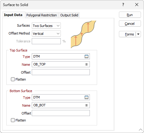
Step 1: Create a Solid from Two Surfaces
- Navigate to Wireframe > Surface to Solid.
- In the form:
- Surfaces: Select Two Surfaces or Single Surface as needed.
-
Top and Bottom Surfaces: Choose the Type and Name for each surface (press
F3to browse). - (Optional) Apply Z offsets or Flattening to either surface.
- Choose the Offset Method and adjust the Tolerance (default is 5%).
- (Optional) Apply a Polygonal Restriction to limit the area.
- Define the Output Solid Type and Name.
⚠️ Important:
To use this function, a suitable pair of surfaces (or a single surface) must be specified. For valid results, the input surfaces should:
- Be created using the DTM tool
- Have similar extents
- Not intersect each other
Note: No automatic check is made to detect intersecting surfaces.
- Click OK to generate the solid wireframe.
Step 2: Calculate Thickness
- Navigate to Wireframe > Calculate WF Thickness.
- In the form:
- Wireframe: Select Single, then choose the Type and Name of the solid generated above.
-
Thickness Direction:
- Choose from Local Plane, Global Plane (Best Fit or Custom), or Both.
-
Global Projection Plane:
- Choose between Orthogonal View (Plan, Looking North, Looking West), or
- Transform with user-defined Dip and Direction.
- Or check Auto-calculate best fit plane.
- Under Output, press
F3and select the attribute field to store the thickness values.

ℹ️ Note: Thickness is stored as a per-vertex attribute. It will not appear in the Properties panel or Wireframe Manager.
Step 3: Visualise the Thickness
- Use Display by Attribute to colour the wireframe based on the thickness values.
- This provides a clear visual representation of areas of varying thickness across your model.

Tips & Notes
- Always validate your wireframes before use.
- Using non-closed or noisy surfaces may produce unreliable or undefined thickness values.
- Flat or planar surfaces should yield zero thickness, but curved/wavy inputs may introduce minor thickness artifacts.
Want to learn more?
Online Help Manuals - Click here for the latest version
Learning Management System - Click here to login or here to request access
Comments
0 comments
Please sign in to leave a comment.